Hello! As I mentioned in my previous post, I focused od clean and publish my weather station code using RF transmission nad NodeMCU v3. Whole my project you can find on GitHub. It split to tree parts:
- rf_encoder – simple methods for encoding and decoding RF messages
- client – code for the device which read sensor data
- server – code for NodeMCU v3 as bridge between RF transmission and MQTT
Encoder
As you may know RF transmission is made from simple text message, so anyone can catch it and read. I was thinking how if kind of information about temperature and humidity should be private and need some protection… I don’t know and I’m not able to answer such question, but I can imagine that in some special cases it should be protected.
So for any case I create simple class which can be modified by anyone for his or er own way or left as it is – means no encrypted.
How to do that? After download repository from GitHub you have to copy whole rf_encoder to your IDE library environment and edit rf_encoder.cpp file in the way as you wish.
include "rf_encoder.h"

String RfEncoder::encode(String deviceId, String message) {
  // put some your logic here
  return deviceId + "|" + message;
}

String RfEncoder::decode(String message) {
  // put some your logic here
  return message;
}
Encode method is used to encode RF message. It receive two parameters: unique device ID (e.g. ABC123) and message as simple text where some parameters are divided by pipe (e.g. 0|21.19|39.25|997.96). Currently I don’t focus on what is in that message, I will describe it later.
To encode such message you can use any kind of encryption mechanism, but you have to be sure that encoded message is not longer than 61 chars, because this is max length of the message. I will not suggest what kind of encryption you should use. Everything depends on you.
You have to remembered that decode message should return text message with uniq device id (e.g. ABC123|0|21.19|39.25|997.96). It is important because this is only parameter which allow the other side to add sensor data to proper device.
Client – sensor device
Configuration
For making whole description simple I called device which make sensor reading a Client.
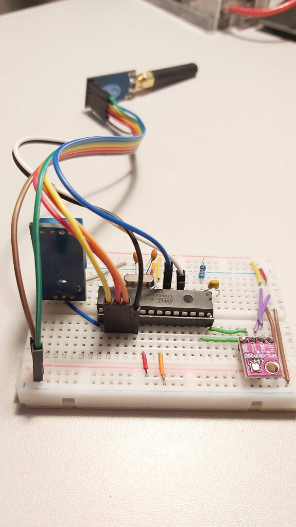
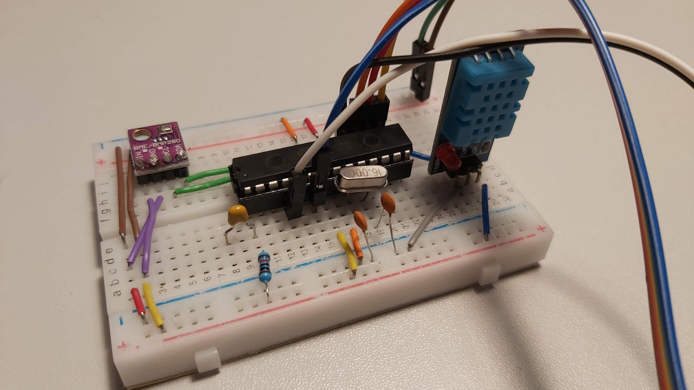
It is build from:
- Atmega328P – this is the core of whole device
- RF Transmitter – CC1101
- DHT11, DHT22 lub BME280 – one or two modules connected to Atmega
- power supply is made of 18650 battery with capacity 8800mAh with 4.2 voltage
Whole project connected looks like below.
Now if we talk about the code, you will find it in client directory. First of all you have to copy configuration.h file as configuration_prod.h and set some parameters in proper way.
First group of parameters is related with RF transmitter and you can set-up it as you wish according to library description SmartRC-CC1101-Driver-Lib.
#define RF_CCMODE 1
#define RF_MODULATION 0
#define RF_FREQUENCY 433.92
#define RF_SYNC_MODE 2
#define RF_POWER 12
#define RF_CRC 1
Here I have to mansion about that if you have other RF transmitter than CC1101, you can use it. The only thing you have to change is to implement below class in proper way in rf.h file.
class RfConnection {
  public:
    RfConnection();
    void begin();
    String waitForReceive(int maxIterations);
    String receive();
    void sendSensorData(String deviceId, String msg);
    void txMode();
    void rxMode();
    void sleepMode();
    void wakeUp();
  private :
    String decode(String input);
    String encode(String deviceId, String input);
    RfEncoder encoder;
};
Next step is to set-up DHT data pin if you use it.
#define PIN_DHT11 9It is not obligatory to set up this data especially if you don’t plan to use DHT device. Other option is to pass this value directly in main code, but I write about it later. Of course you can use different sensor than DHT11, DHT22 or BME280. To do that, you have to add new SensorType value in sensor.h file and add additional implementation in Sensor class. If you would like you can share that code and set some pull request on GitHub.
After that you have to set up time interval between two sensor data readings.
#define SLEEP_INTERVAL_SEC 300This value is setup in seconds and it is some approximated value, because of some sleeps during running code. Additionally Amtega328 can go deep sleep for 8 seconds or forever (it needs some external wake up signal and more power supply). I use the first option and it also make that time no so equal, because every 8s Atmega328 wakes up and checks if the time from last reading is bigger than setting interval. If not Atmega328 is going deep sleep once again. If yes, read sensor data and send it through RF transmission. After all it is going deep sleep and the process starts once again.
The last thing that you have to configure is unique device id.
#define DEVICE_UNIQUE_ID "ABC123"The ID should be unique in whole your system, contains only letters and digits and not longer than 6 chars.
Now you are able to upload your code to your Atmega328, but before that you have to set up one thing in main code. In client.ino file we have such lines.
Sensor sensorOne(0x76);
Sensor sensorTwo;
It is responsible for turning on and off first or second sensor module. The first line in above example is turn on first sensor. It is BME280 with its ID 0x76. The second sensor is marked as off, but if you would like use as second sensor DHT 11 these two lines should be replaced with:
Sensor sensorOne(0x76);
Sensor sensorTwo(DHT11_PIN, DHT11);
The first parameter is data pin of DHT sensor and the second is type of DHT device in that case it is DHT11.
And that is all when we talk about configuration, no is real time to upload code and focus on how it works.
What do it the code
As I described it above the microcontroller will be waked up approximately every 8 seconds. Try to make sensor reading and go deep sleep once again.
What about message that is send from the client. As I mention previously it is only text message (which can be encoded), but this message contains few information divided by the pipe char:
- device unique id – device id contains 6 chars (letters and digits)
- sensor number – digit which represent sensor connected to device, by default 0 means first sensor, 1 – second sensor, if you want more it is possible to add more
- temperature – temperature in Celsius degrees (rounded to two decimal places)
- humidity – in percents (rounded to two decimal places)
- pressure – in hPa (rounded to two decimal places), if device do not have such sensor it returns null
For example it could be something like that “ABC123|0|21.19|39.25|997.96“.
Such kind of message is delivered to Bridge.
Bridge
Bridge as the name suggests is device which connects real server with the RF device and is able to change RF signal to some MQTT data.
In my case Bridge is build from:
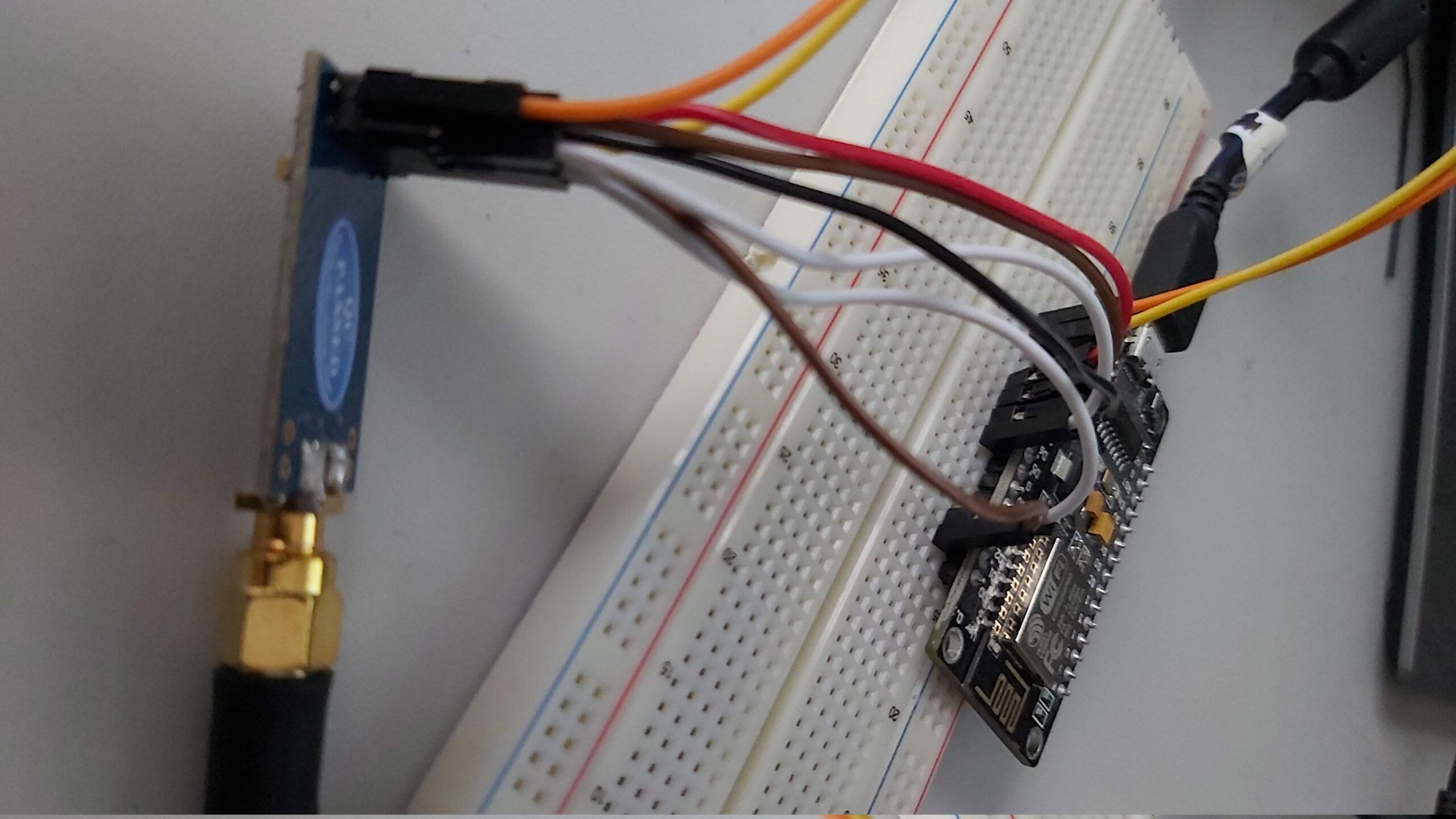
- NodeMCU v3 – as the core of the device which use WiFi connection
- Receiver CC1101 – RF receiver
All after connecting look like below.


Generally in that case connection is very simple and compatible with library documentation – look at the image.
Configuration
Before you upload code to the NodeMCU you have to create configuration file configuration_prod.h based on default configuration.h file and setup proper parameters.
WiFi configuration. Your WiFi session ID and password.
// WIFI SETTINGS
#define SSID "YOUR_WIFI_SESSION_ID"
#define PASSWORD "YOUR_WIFI_PASSWORD"
Next configuration of RF receiver should be in line with Client configuration.
#define RF_CCMODE 1
#define RF_MODULATION 0
#define RF_FREQUENCY 433.92
#define RF_SYNC_MODE 2
#define RF_POWER 12
#define RF_CRC 1
Follow that you have to set up configuration of yours MQTT server.
#define MQTT_SERVER "MQTT_SERVER_IP"
#define MQTT_PORT 1883
#define MQTT_USER "MQTT_SERVER_USERNAME"
#define MQTT_PASS "MQTT_SERVER_PASSWORD"
Ant the last one is information about number of devices connected to this Bridge and how much of last results should be stored in memory.
#define MAX_NUMBER_OF_DEVICES 10      // max 10
#define SENSOR_DATA_LIST_LENGTH 20    // max 20
Now you are ready to upload the code.
How it is working
Bridge as I mention previously is responsible for catching all RF transmissions, decode them add information about time (in that case timestamp) and dew point temperature.
All that data is send to MQTT server in topic ws/DEVICE_UNIQUE_ID/SENSOR, where DEVICE_UNIQUE_ID is symbol of the device. Message that is send to MQTT server looks like below.
{
    "uniqId": "ABC123",
    "sensor": "0",
    "payload": {
        "time": 1607006383,
        "temp": 23,
        "hum": 60,
        "pressure": 999.72,
        "dewPoint": 14.79
    }
}
Bonus
Bridge has additional option. It expose HTTP server on port 80, where you can find all data that it receive and decode grouped by device.
Summary
In that case we arrived to the end of that project. As I wrote in previous post data from MQTT are subscribed for Home Assistant and my own server (this one only collect whole data but unfortunately it not present pressure and dew point yet – waits for upgrade).
Maybe it is not perfect project but it is working. I have few ideas to upgrade it but maybe later when I will have some time. So if you have any ideas or some ready code do not hesitate to contact me or send some pull request on GitHub.